The site at Harrow Weald was selected around 1946 to provide a repeater station for the
1949 900 MHz London to Birmingham television link .
In the original plan Harrow Weald would have been the termainal station with cable
to Museum Exchange. The link operated on 900 MHz and provided an alternative to the coaxial cable which was also
available between London and Birmingham.
There do not seem to be archive photos showing the original arrangements at Harrow Weald but similar equipment
was used at all intermediate sites and the subsequent development seems to have mirrored that at Dunstable where
2 GHz links replaced the 900 MHz system by the early 1960s and a new tower carrying horn antennas was in place
a few years later. The site thus continued to be the "first hop" on the Birmingham route once the Post Office
Tower became operational.
Old OS maps from the period 1963 to 1965 show a "mast" of large cross-section and three smaller buildings. These do not correspond
to the present-day site, which is slightly to the west. It appears an adjacent plot was used for the late 1960s
development. The site is surrounded by trees and it's difficult to see from aerial photos whether traces of the
older buildings remain. Two horns and several large dishes were in place in November 2007 but most likely have
been removed subsequently. A local DAB "filler" transmitter was added in 2005 but the site otherwise seems to be used for
local linking by BT.
Photos
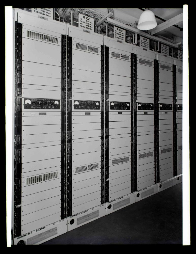
1961
Copyright BT Heritage [TCB417/E 25806]
A group of six GEC 2 GHz transmitter/receiver racks. The BT Archive catalogue record suggests this equipment had Post Office designation RS 9/4. This was the "second generation" equipment providng several channels to be used either for television or telephony as required.
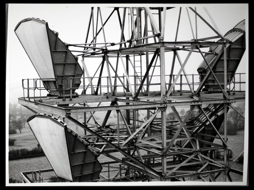
1965
Copyright BT Heritage [TCB417/E 30640]
This photo is indexed under Dunstable in BT Archives however these are "small" horns and we
believe this shows the installation at Harrow Weald.
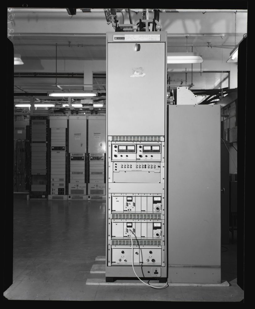
1970
Copyright BT Heritage [TCB417/E 52753]
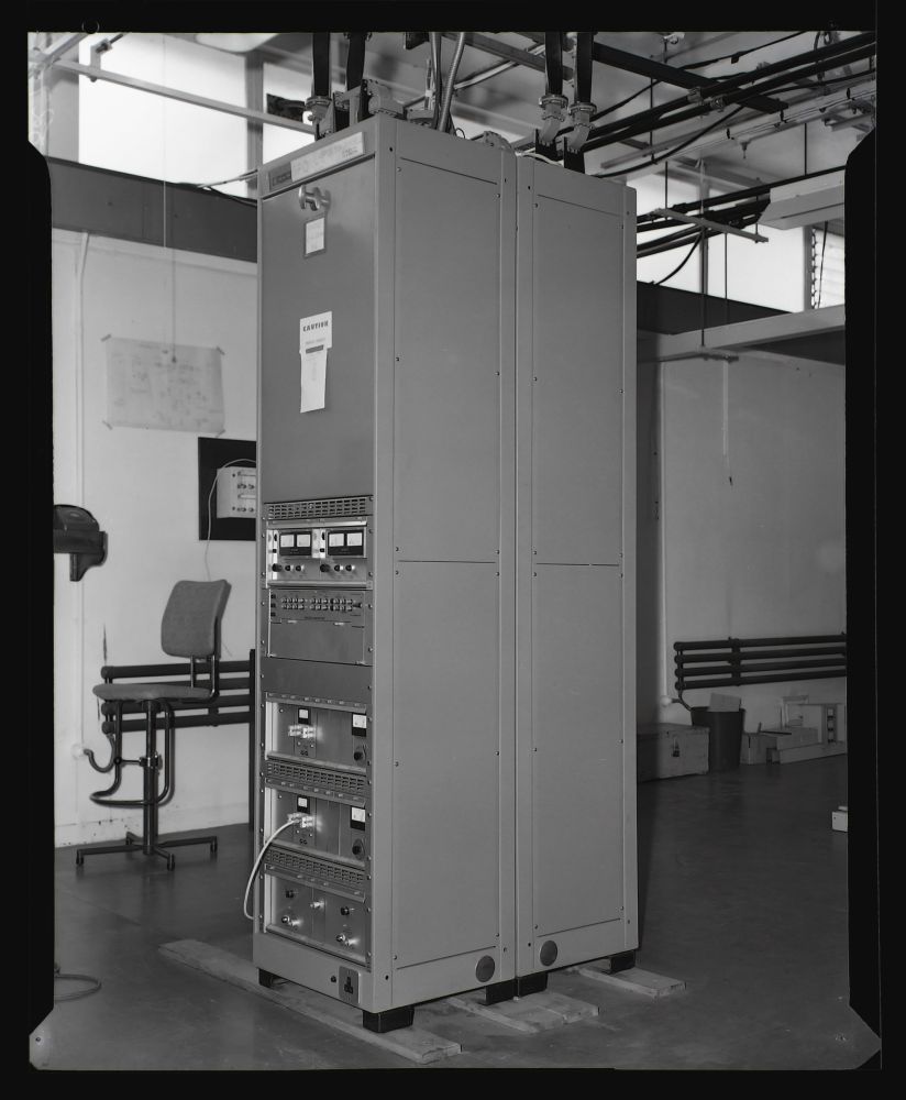
Pye M717 equipment was installed on some routes in the late 1960s to carry additional
colour TV circuits. This equipment was designated RS 10/28 and used transistors except for the
output stage. The label reads "GPO UPPER SIX PHASE 4".
Copyright BT Heritage [TCB417/E 52752]
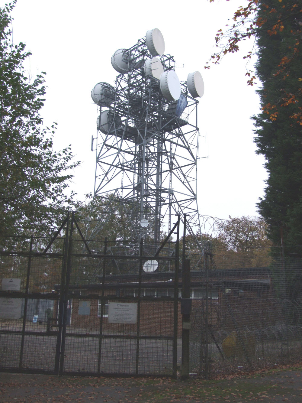
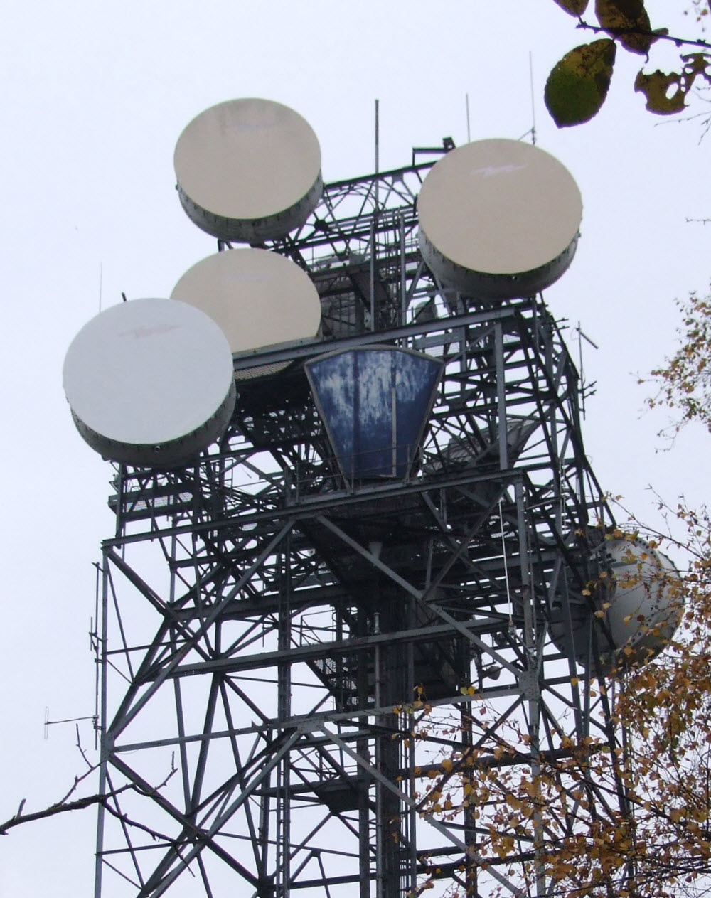
November 2007
Copyright Roger Piper
The tower, as at Dunstable, is similar in concept to the "standard tower" with "steps" to allow horns to be mounted at
different levels. One horn remains in each direction, together with four large dishes. The building, of the standard
design, has been finished in red London brick.
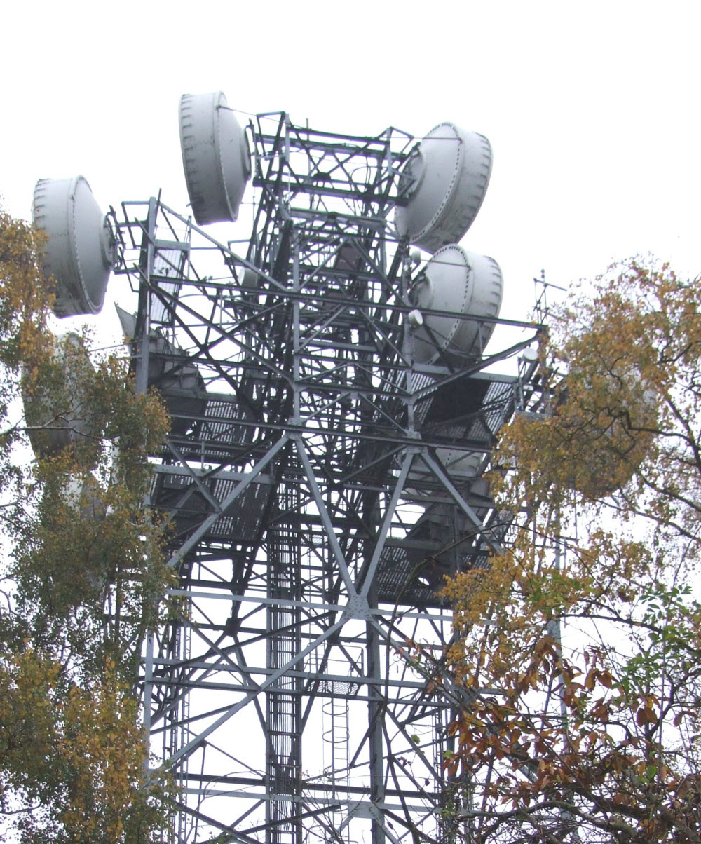
Copyright Roger Piper
A profile view shows the narrower top section of the structure and the way in which the horns are mounted above a square
"grillage" with the bottom of the tapered section taken through a hole in the centre. This allowed the (circular)
waveguide to run vertically to ground level. Two more horns were originally mounted on the upper level, see 1965 photo.